How to Draw Circle Centerline in Autocad
![]() This functionality is currently available only on browser.
This functionality is currently available only on browser.
![]()
Onshape provides tools for creating sheet geometry: drawing entities like lines and centerlines, created on the sheet outside of a view and meant to represent some part of the 3D model.
When creating views of parts and surfaces, centerlines are automatically hidden on circular geometry such as holes, cylinders, and spheres. View these centerlines using the view context menu. See Show/hide centerlines.
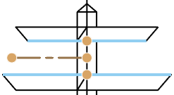
![]() 2 point centerline
2 point centerline![]()
Create centerlines using two points on your drawing, including the end points on another 2-point linear centerline.
- Click
 .
. - Select two points to establish a centerline. Note that you are able to use snap points, but it is not required.
When aligning dimensions and annotations, you can hover over edges, midpoints, or other lines to activate red inference points. Use the inference points to snap the location of the entity when creating or dragging a dimension or annotation. Similarly, you can move the mouse vertically or horizontally over views, lines, dimensions, or annotations to activate pink vertical and horizontal inference lines. Use these inference lines to align the location of the entity vertically or horizontally from the desired referenced annotation.
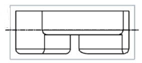
![]() Edge-to-edge centerline
Edge-to-edge centerline![]()
Create centerlines using two edges or two concentric arcs on your drawing.
- Click
 .
. - Select two edges or two concentric arcs with which to establish a centerline.
Adjust the length of the centerlines by clicking and dragging the grip points at the end of the centerline.

![]() Removing centerlines
Removing centerlines
- With no tool selected, click the centerline (it appears highlighted).
- Press the Delete key.
![]() Modifying centerlines
Modifying centerlines
- With no tool selected, click the centerline (it appears highlighted).
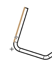
- Click and drag an end point to resize the line:
Note that centerlines may be dragged below the distance between the reference points.
- Click and drag a snap point to move the line:
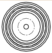
![]() 3 point circle centerline
3 point circle centerline![]()
Create a circular centerline for a bolt circle diameter.
- Click
 .
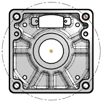
. - Click each of 3 points (centers of the holes, end, mid, or quad points). The illustration shows the centerline in process (the plus signs represent the selected points):
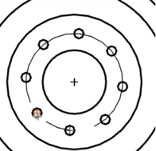
The illustration below shows the centerline selected; you can see which holes help define the centerline:
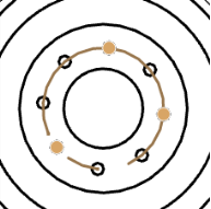
The centerline can now be dimensioned.
When aligning dimensions and annotations, you can hover over edges, midpoints, or other lines to activate red inference points. Use the inference points to snap the location of the entity when creating or dragging a dimension or annotation.
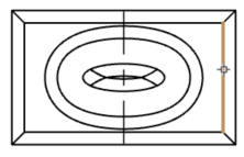
![]() 2 point circle centerline
2 point circle centerline![]()
Create a circular centerline using two points.
- Click
 .
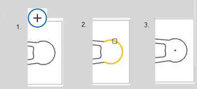
. - Click a point to mark the center of the centerline (this does not have to be an actual circle center, you can snap to any point like an end point or midpoint as well).
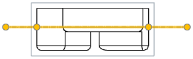
- Click a point to mark the circumference of the centerline (like the center of a bolt hole).
The first illustration shows the centerline in process (the orange highlighting represents the selected points):
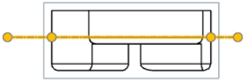
You are now able to dimension the centerline.
When aligning dimensions and annotations, you can hover over edges, midpoints, or other lines to activate red inference points. Use the inference points to snap the location of the entity when creating or dragging a dimension or annotation.
![]() Centermark
Centermark![]()
Place a mark in the centers of circles and arcs for visibility when printing and as a reference point for dimensions.
- Click
 .
. - Click the edge of a circle or arc:
To delete a centermark, click to select and press the Delete key. See centermarks for more centermark editing options.
![]() Virtual sharp
Virtual sharp![]()
Create a virtual sharp associated with two linear edges. Virtual sharps are fully associated with the geometry and update appropriately with changes to the geometry.
- Click
 .
. - Select first linear edge.
-
Select second linear edge.
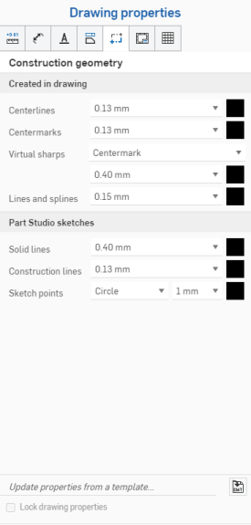
Dimensions are to the intersection of the cross only. To change the visual style of the virtual sharp from Centermark to Edge extension, open the Properties flyout:
![]() Line
Line![]()
Shortcut: L
Create lines in your drawing.
- Click
 .
. - Click to begin the line.
- Drag and click to define subsequent line segments.
- Escape to end the line and exit the tool.
Note that horizontal and vertical inferencing lines appear as appropriate:

Each segment in a series of connected lines is a separate entity.
As you draw, snap points appear on existing objects to aid you in line placement. Click once the snap points appears to connect to it automatically.
There is no need to click directly on the point once it is visible. While moving the mouse to place the line, you'll notice thin, dashed lines as the cursor passes near other entities. These are inferencing lines that you are able to align the line to; simply click when you see the line appear to align to that inferencing line.
![]() Spline
Spline![]()
Create a spline through multiple points.
- Click
 .
. - Click to begin the spline.
- Click to select additional points for the spline to fit to in the view.
- Double-click or press Escape to end the spline.
As you draw, snap points appear on existing objects to aid you in spline placement. Click once the snap points appears to connect to it automatically. As with any spline, you are able to drag the points to reshape the spline.
When aligning dimensions and annotations, you can hover over edges, midpoints, or other lines to activate red inference points. Use the inference points to snap the location of the entity when creating or dragging a dimension or annotation. Similarly, you can move the mouse vertically or horizontally over views, lines, dimensions, or annotations to activate pink vertical and horizontal inference lines. Use these inference lines to align the location of the entity vertically or horizontally from the desired referenced annotation.
![]() Spline point
Spline point![]()
Add points along a spline.
- Click
 .
. - Click along the spline to set additional points.
- Drag and click to define subsequent line segments.
- Press Escape to exit the tool.
Drag spline points to modify the spline.
As you draw, snap points appear on existing objects to aid you in point placement. Click once the snap points appears to connect to it automatically.
Was this article helpful?
Last Updated: June 06, 2022
Source: https://cad.onshape.com/help/Content/draw-tools.htm
0 Response to "How to Draw Circle Centerline in Autocad"
Post a Comment